
The Build
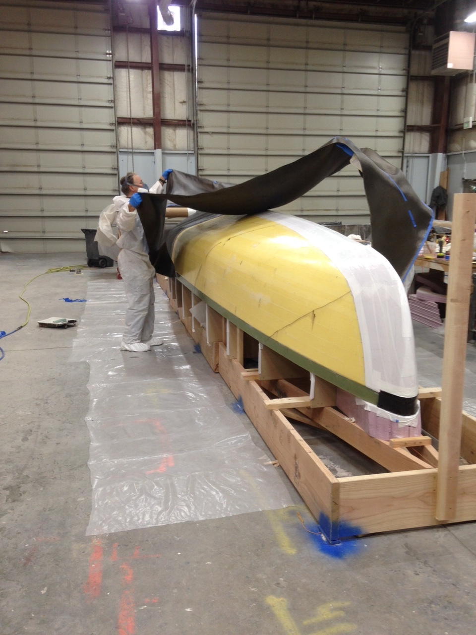
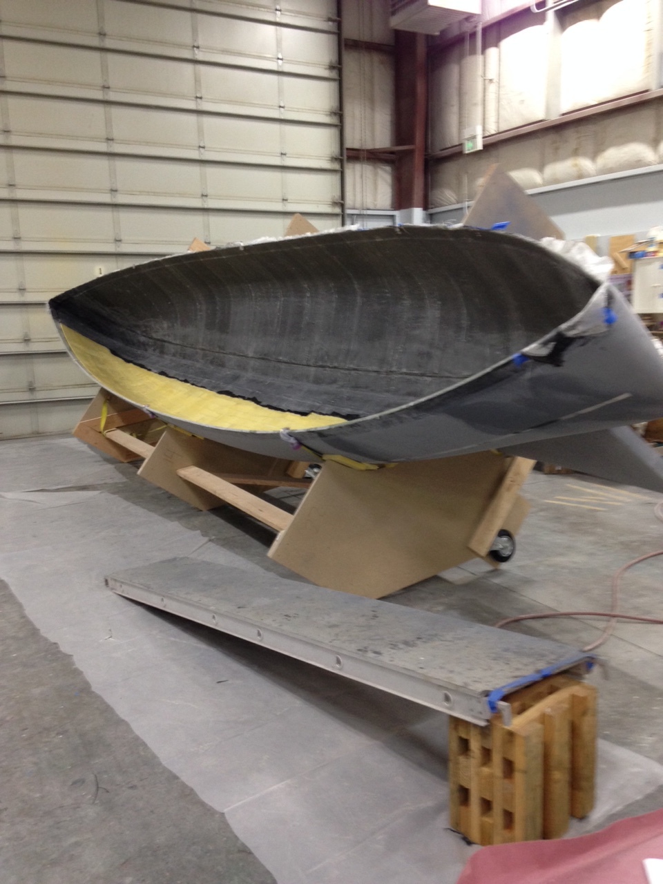
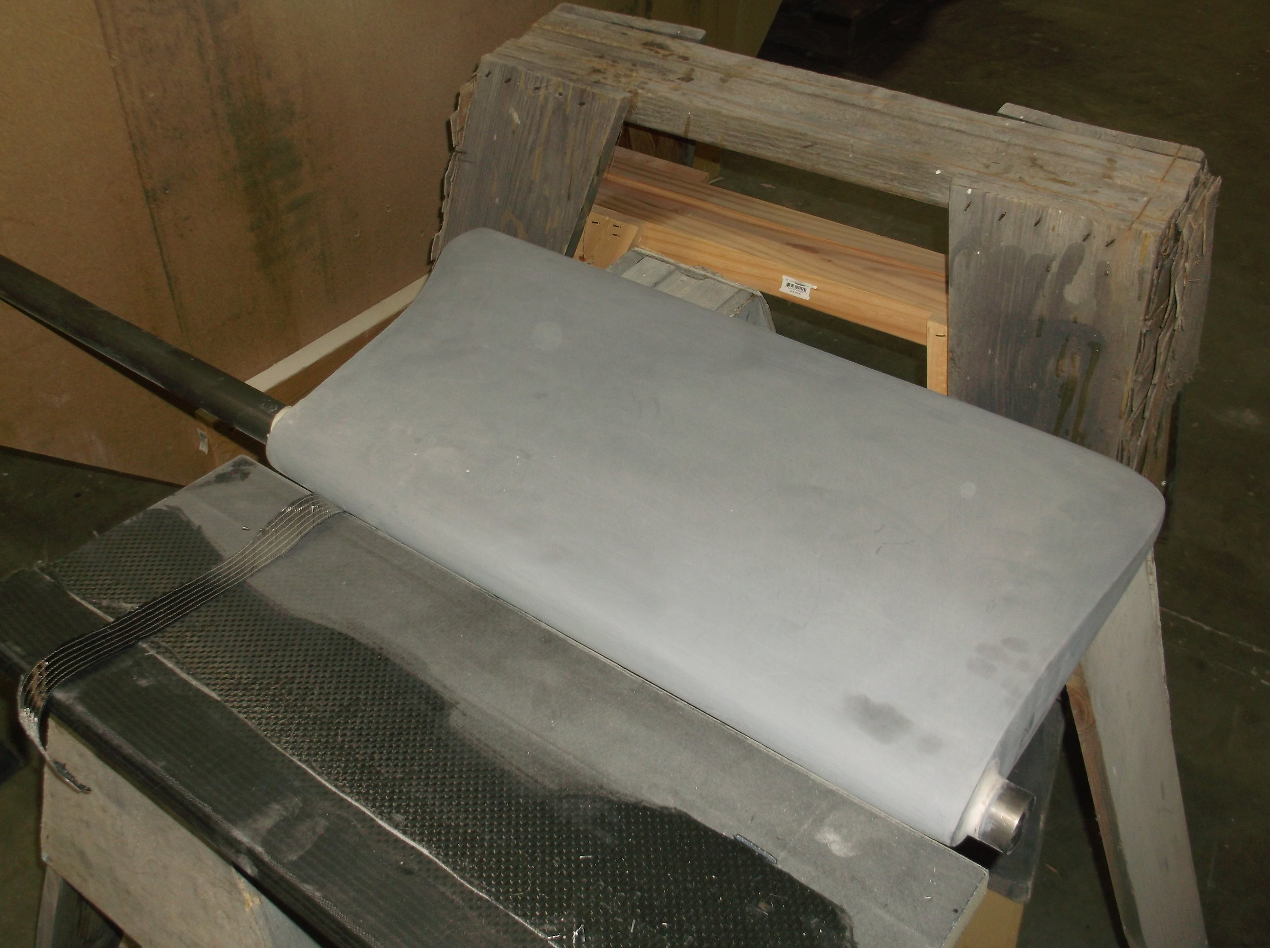
The construction was by Schooner Creek Boatworks in Portland, OR using carbon fiber and a foam core. The hull and cabin tops were constructed by the strip planking method. The interior deck, bulkheads and other components were constructed using the infusion method. Below you'll see the initial jig in place for the hull. It was constructed based on the design drawings using section cutouts along the length of the boat. You can also see the pink solid foam where the laminate will be 100% carbon (no foam core in those areas). Once the jig is complete, strip planking begins. You can see the yellow strips of foam core that rest between the inner and outer layers of carbon fiber. The grey piece is solid fiberglass defining the top edge of the hull, and will also serve as the joining point for the top cabins once turned right side up. Once the foam core is fully in place, it's then epoxied and sanded fair in preparation for the carbon fiber. You can also see the application of carbon fiber onto the hull using the wet layup method, followed by a sacrificial layer of glass cloth for additional filling and fairing.


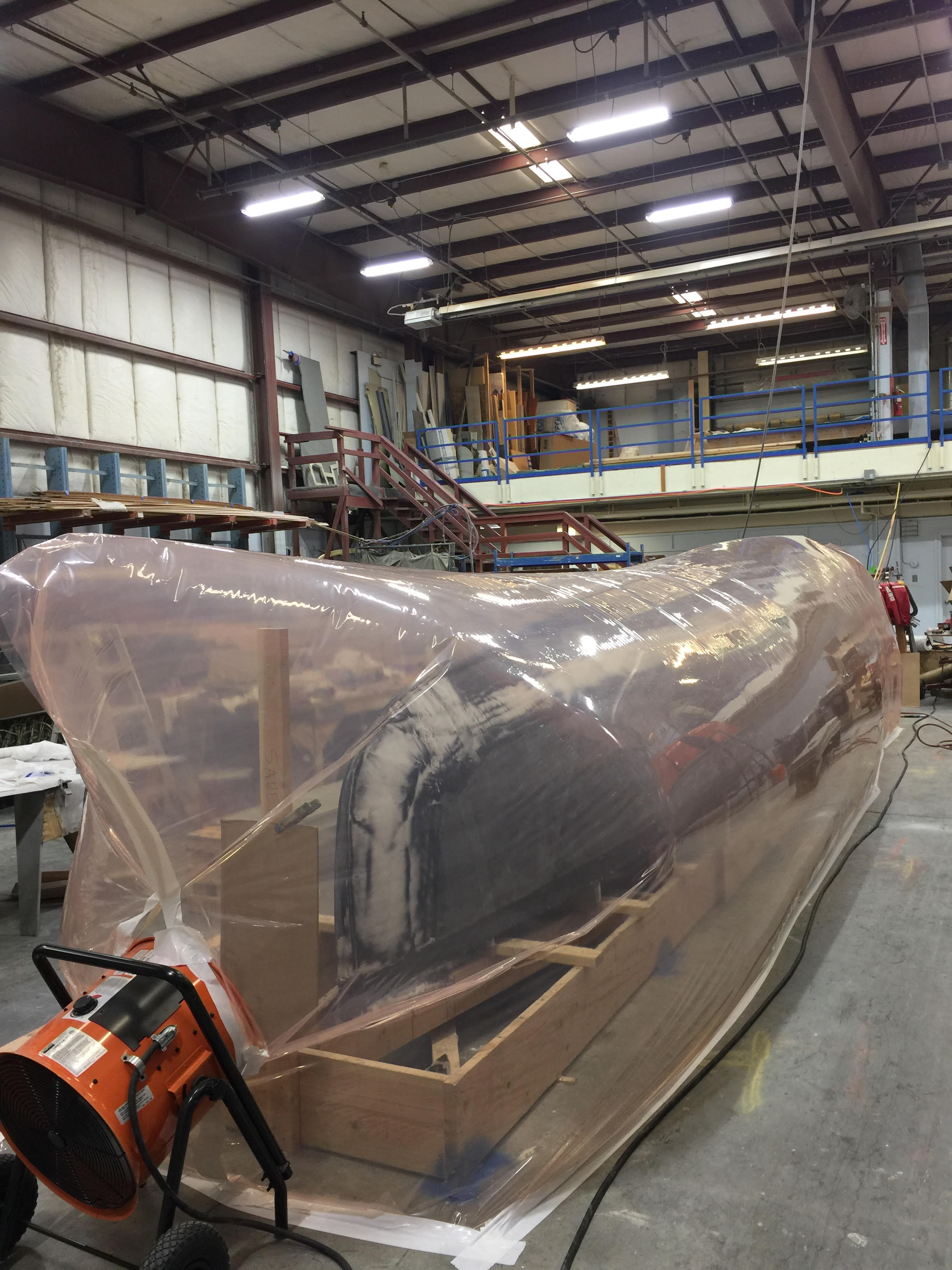
A final layer of peel ply is applied to the center of the hull in preparation for bonding the keel. Once complete, the entire hull is post-cured by bringing it up to a specified temperature in order to optimize the structural properties. You can also see the initial foam cutout of the keel. It's then layered with carbon and bonded to the hull. Once complete, sanding and fairing of the entire hull and keel begins.


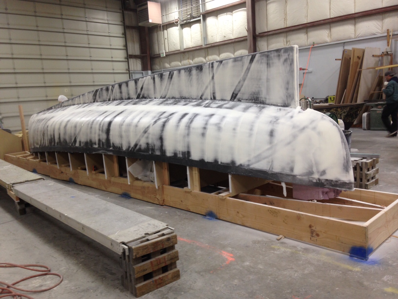
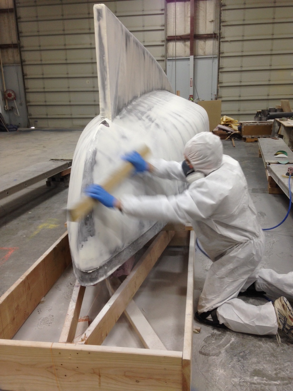
When the fairing is complete, an additional layer of epoxy is applied to the hull in preparation for the finish paint. The finish paint will occur at a later date, once the construction is complete. You can also see the steps involved in the preparation for turning the boat right side up, removing the initial jig and rolling it over. When the initial jig is removed, application of carbon fiber to the interior of the hull can commence using the same wet layup method.


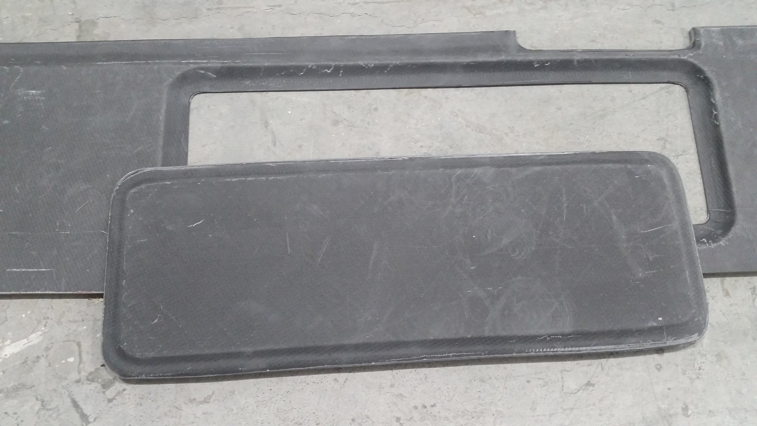
Once the hull is complete, work can begin on shaping foam for the interior deck and bulkheads. Instead of the wet layup method, the interior deck, hatches and bulkheads will be layered with carbon fiber by infusion under sealed vacuum bags. In order to simplify infusion of the bulkheads, frames were fitted within the hull using wood in the appropriate shapes, then strategically placed on the foam and outlined. This way, all the bulkheads can be infused in one large section then cut to shape once the infusion is complete.


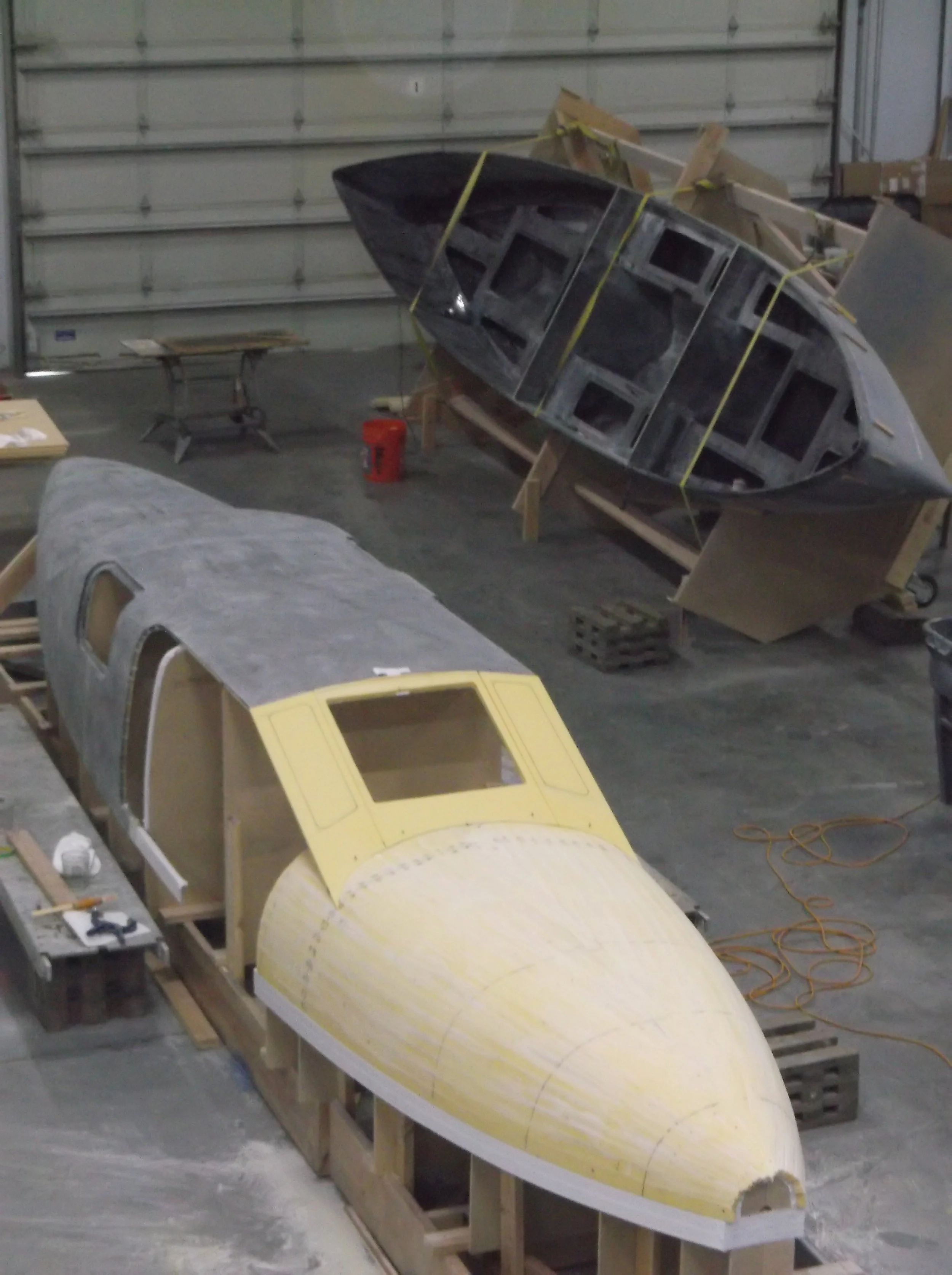
With the infusion of the bulkheads and interior deck pieces complete, work begins on cutting the shapes to size, removing excess carbon, and sanding down pieces for a perfect fit. The bulkheads are initially glued to the interior of the hull, then the corners between the hull and bulkheads are rounded with a mixture of silica and microballoons. This allows for a stronger fit when secured into place with carbon fiber. The bulkheads are secured by tabbing them into place with two layers of carbon fiber, a layer of glass cloth, and a layer of peel ply. We also begin construction of the jig we'll use for strip planking the upper cabins. They'll be constructed using the same method as the hull. However, the shape of the cabins present a different challenge.


While the construction of the upper cabins continue, work also moves forward on installing the interior deck. This is done by prefabricating the tabbing that will secure the bottom of the interior deck to the top of the bulkheads. This tabbing is the same structure and material as the tabbing that secures the bulkheads to the hull. Once the prefabricated tabbing is complete, it's then attached to the top of the bulkheads. Once dry, the deck pieces are laid on the tabbing then secured.


With the deck complete, focus turns to the upper cabins. Strip planking commences using the foam core once the jig is complete. The jig is created using the same method as the hull by using section cutouts based on the designer drawings. Strip planking of the cabins requires a bit more finesse due to the unique shape and curves built into the design. After the strip planking is complete, application of carbon fiber commences on the exterior of the cabins using the wet layup method.


Application of carbon to the exterior of the aft cabins is now complete. The cabins are then fit tested on the hull prior to completing the interior application of carbon fiber. The forward and aft cabins are connected by 3" carbon fiber tubes both for structural integrity of the hardtop and to act as electrical conduits. They also support the aft facing windows. To facilitate the installation of the carbon tubes and cabins, the top sections are separated into three pieces. Once fit testing is complete, the application of carbon to the interior of the cabins begins. The cabins are then secured to the hull and the carbon tube assembly is adjusted for a proper fit.


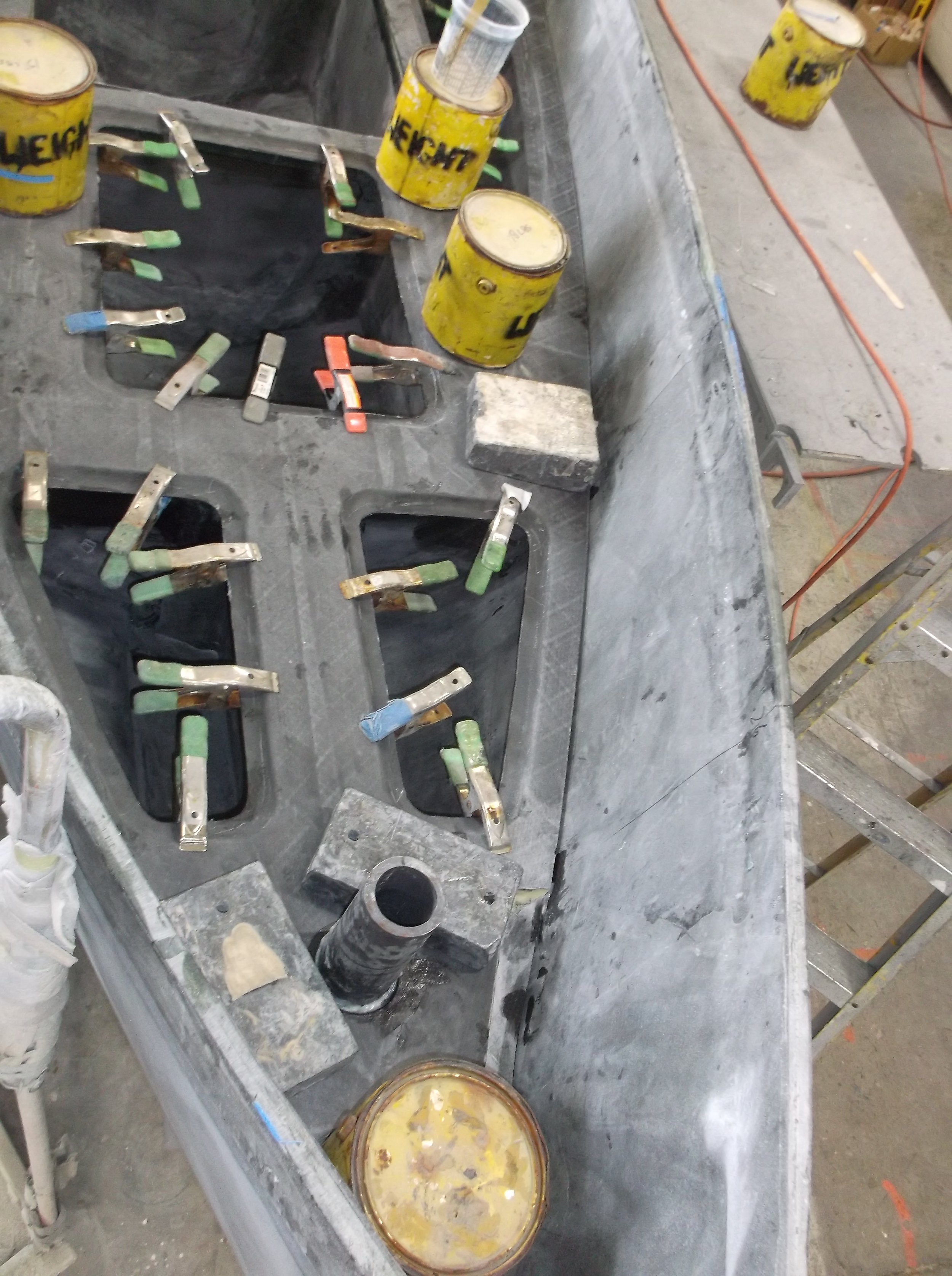
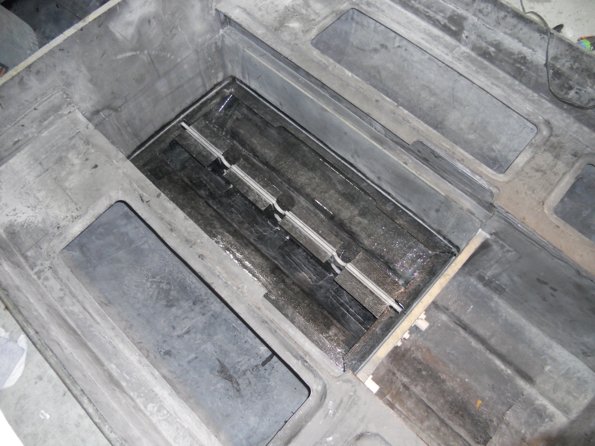
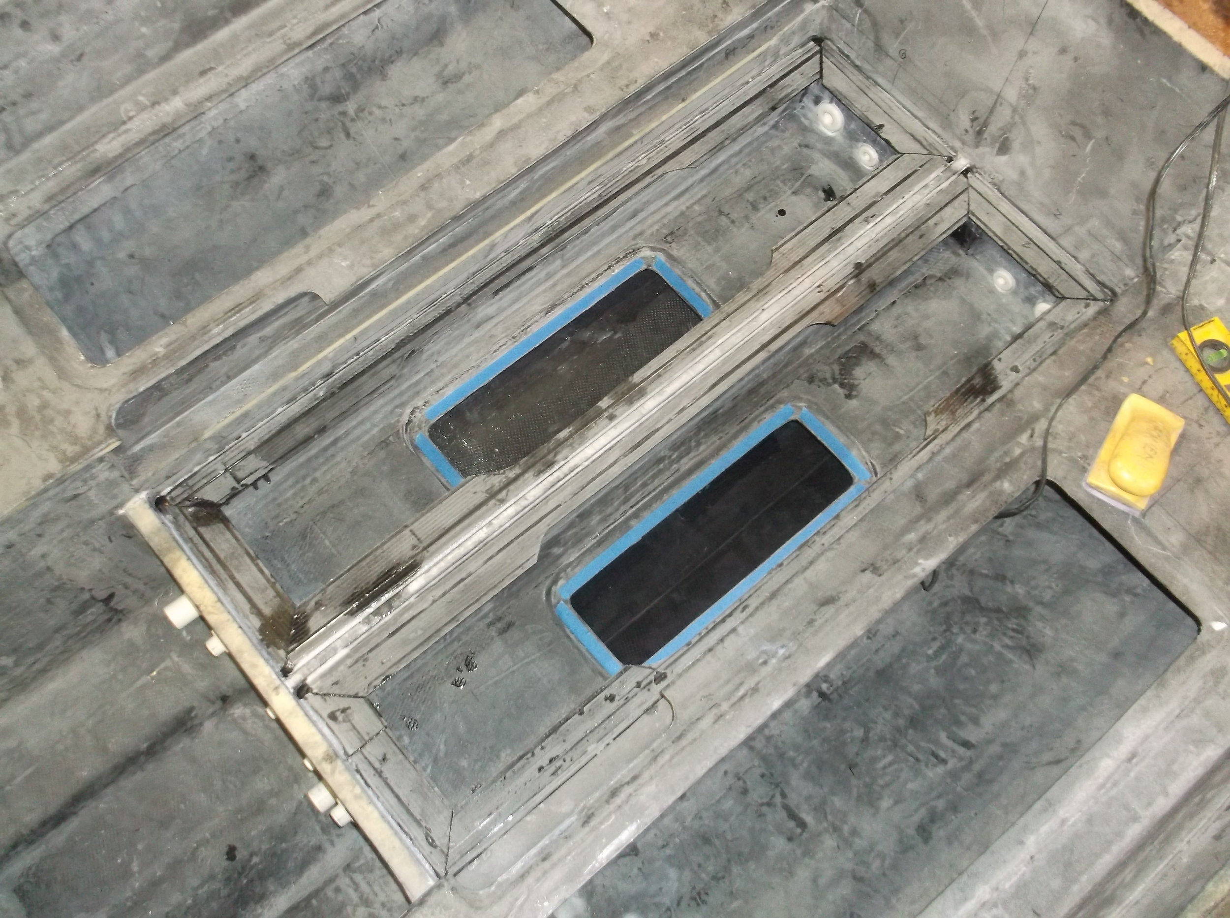
Once the cabins are fitted and secured, work then begins on completing interior details, starting with the water tanks. The water tanks rest below the sliding seat area with the salt water ballast tank on the bottom and the fresh water tank directly above. Below you'll see the steps involved in installing the salt water baffle, plumbing fittings, and sealing lids. Fresh water will be fed directly into the fresh water tank using a reverse osmosis desalination pump. You can also see the above deck storage cubbies initially glued into place.


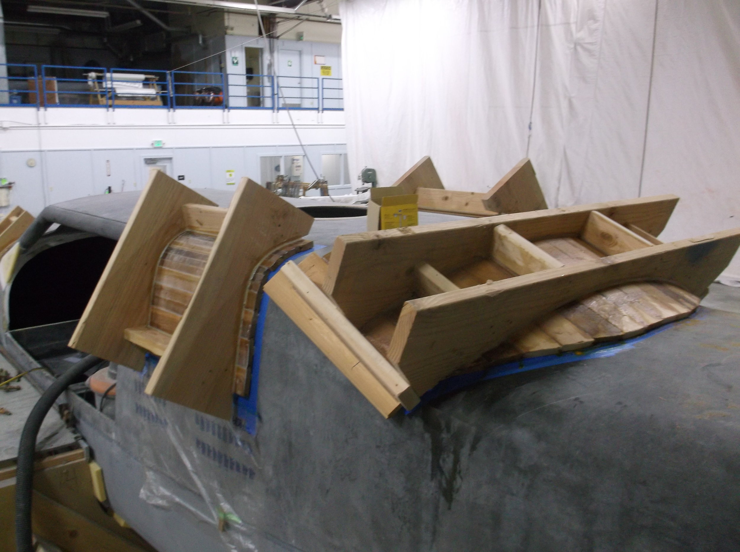
Next, the bulkheads sealing the forward and aft cabin from the center rowing area are fitted and glued into place. Due to the custom design of the cabin windows, molds are created out of wood for properly shaping the windows. More details are completed to include fabricating and installing brackets for the reverse osmosis desalination pump and the battery tray. To better streamline the transition from the carbon tubing and the aft cabin, a small wedge is created and layered with carbon fiber. This will provide better protection in the rowing area during inclement weather.


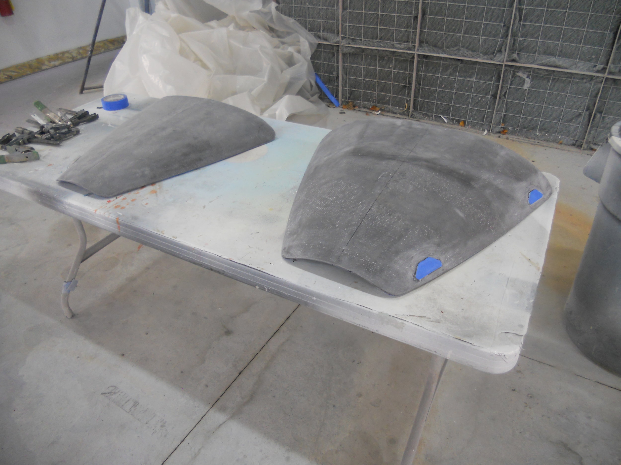
The hardtop is still a point of concern. The original design calls for permanently attaching the hardtop to the carbon tubing. However, we are looking for potential methods to hinge the top, allowing for a fully open view above the rowing area if desired. Since the hardtop will support solar panels, it presents some challenges. Below is one idea. Additionally, the bow and stern hatches are cut to shape and prepared for hinges. With the cabins and tubing permanently attached to the hull, and the interior carbon components installed, the boat undergoes a final post cure. By heating the entire structure, it optimizes the structural properties of the carbon fiber. Once complete, the boat is prepared for its first coat of primer!


Once the first coat of primer is applied, the final fairing is completed. We reinforced the gunnel with additional G10 fiberglass to support the oarlocks, then sanded everything fair. We also assessed the placement of the solar panels, electronic equipment, and primary compass. You can see the sliding seat inserted above the water tanks, padding to follow. During testing of the oarlock placement, we decided a 6-8 inch outrigger is required due to the weight and length of the oars. We also fabricated a custom spray rail made from carbon fiber and foam. Lastly, we completed the exterior paint. Looking good!


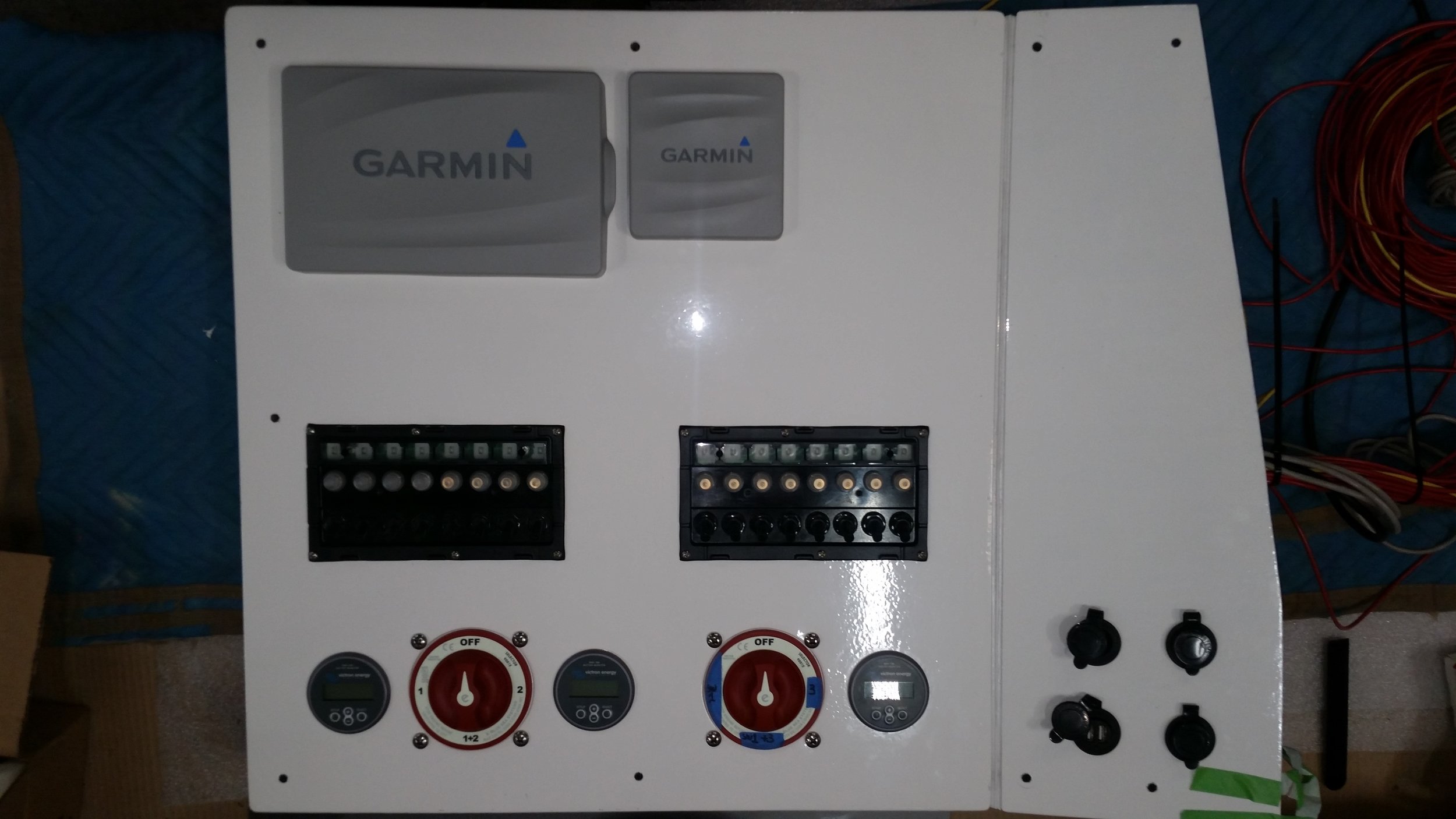
Once complete with the exterior paint, we turned to installing the custom windows, fitting the electrical box, and finishing the interior deck hatches. The hatches are fitted with G-10 blocks to secure the hatches in the appropriate position. We then made the cutouts for the latches that'll lock everything in place. We also created a custom electrical box to house all the electrical components I'll be using. We tabbed the box onto the structure of the hull and then cut the appropriate pathways for future wiring. The windows were also installed; it looks like the molds we used made for a perfect fit!


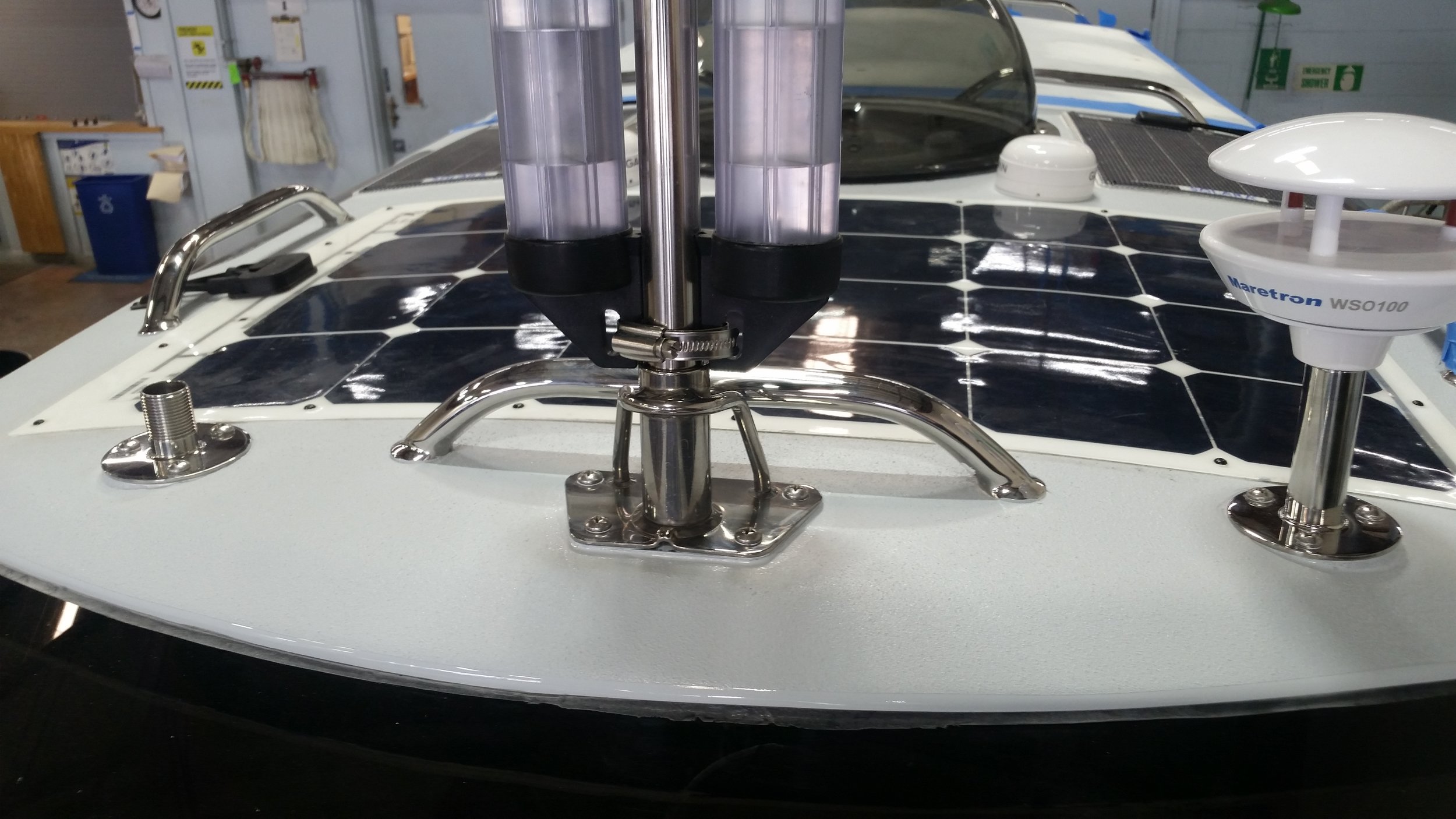
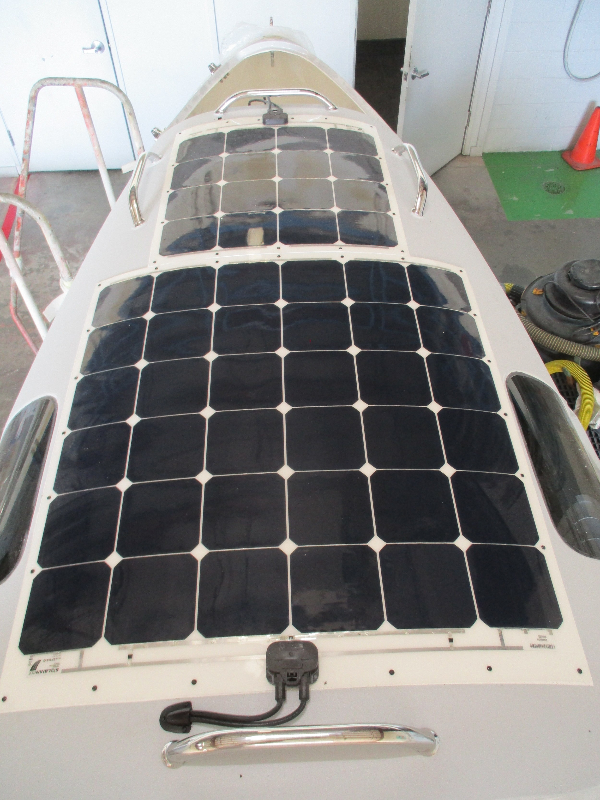
Here you can see a nice view of where the solar panels will live, nearly 600 Watts of output at peak performance. Since the boat is constructed of carbon fiber, it's susceptible to galvanic corrosion wherever there is contact with metal. In order to prevent the corrosion, we separated the bolts and fasteners with G-10 material or oversized the bolt holes and filled them with an epoxy mixture (2-Part epoxy, silica and microballoons). This is another area where there is an appreciation for the amount of work involved in creating a custom boat. We fitting backing plates for the exterior antennas, anemometer, U-Bolts, and radar reflectors. Once complete, we painted the interior with two coats of standard bilge paint. And finally, you can see her getting ready for the Portland Boat Show!


With the majority of the construction complete, we now turn to installation of the systems. Below you'll see the electrical components coming together. We have wiring starting to feed into the electrical box installed in the forward cabin from the antennas, the battery compartment, the solar panels, the steering, the lighting, the AIS (Automatic Identification System) and all other electronic components. We have three 110 Ah deep cycle marine batteries installed, all being charged directly from the solar panels through independent charge controllers. Everything will be controlled from the electrical panel.


Here we are finalizing the fore and aft cabin hatches. The rudder is installed in the aft cabin and we begin configuring the electric and manual steering systems. The outcome was basically invented by Jake at Schooner Creek - he did an amazing job! You can see the work involved with determining the correct angles, fabricating the custom fittings, and trial and error mock-ups.


Below we finalized the outrigger and oarlock setup and checked the oar positioning in relation to the design water line (DWL). We are also looking for a solution for storing the spare oars. At 10' 10", they are too long to fit in the aft cabin, and very cumbersome within the forward cabin. You can also see the initial setup for the plumbing configuration. We have three thru-hulls - one for the electric water maker intake, one for the salt water ballast intake, and one for the DST110 Depth-Speed-Temperature transducer.


We took the boat to the Portland Boat Show once again, this time much further along in construction. I was interviewed by a couple of news agencies while there, which was an interesting experience. We had the christening ceremony, the initial stability tests, and the inaugural row.


Below is a short description of the plumbing setup aboard Emerson. I used a Spectra Ventura 150 Watermaker throughout the entire 336 day journey without any problems whatsoever. Since I had two water tanks on board (24 gallons total), I only had to run the system once every 4 days, with a full three minute fresh water flush each time.
I would run the watermaker for about 2-3 hours, which was plenty of fresh water to last 4 days. I would never go more than 5 days without running the system, due to the potential of organic growth within the membrane. I changed the pre-filter twice over 11 months, and the sea strainer once. Otherwise, there was no required maintenance other than taking care to operate the system in accordance with Spectra recommendations, including the fresh water flush. Overall, I was very satisfied with the system and would use Spectra again in the future!
Below is a video explaining the components of the electrical system aboard Emerson. The system was powered by nearly 600 Watts of solar power at peak performance. Those solar panels charged three 110 Ah deep cycle marine batteries, which provided power for all electronic devices on board.
The system held up remarkably well despite water intrusion issues on board. At one point the entire battery compartment was filled with sea water, but the system managed to keep running after some minor repairs. The power output of the solar panels was more than enough. If it was a clear day and the sun was unobstructed, I could run the 9 Amp watermaker and still get positive amperage flowing to the batteries.